Indexable Insert Chipbreaker Cross Reference
Note: Chart is intended to be used as a guide to chipbreaker selections. The information listed is approximate and all specific information should be obtained from the manufacturers.
Kennametal, Seco, Valenite, Iscar, Sumitomo, Stellram, Hertel & Interstate are currently represented in the MSC Big Book.
| Operation | Kennemetal | Sandvik | Seco | Walter-Valenite | Iscar | Hertel | Sumitomo | Stellram | Mitsubishi | Tungaloy | Interstate | |
|---|---|---|---|---|---|---|---|---|---|---|---|---|
|
Fine Finishing |
FF |
PF |
MF2 |
C5, F2 |
RF,FF |
BF,HF,BFM |
ESU |
1A, 62 |
SH |
TS, TSF |
IF, P |
|
|
Fine Finishing |
UF |
UF, QF |
FF1 |
PS5 |
SF, SM |
HF, CFM |
ESU, ESX |
-62 |
FV, FW |
1, TSF |
||
|
Finishing |
LF |
PF |
F1 |
F5, PF2, PF4 |
NF |
AF, AM, LF, HMF |
ESU, ESP, ESX |
-62 |
FV,FS MQ |
PS |
2C |
|
|
Finishing |
LF |
MF,-23 |
MF1 |
F5, NF3, NF4 |
TF |
AF, AM, LF, HMF |
EGU, ESX, EUX |
3F |
SH |
TM |
||
|
Finishing |
FP |
MF1 |
F5 |
PP |
F, HF, HMF |
EGU, ENK |
2B |
SH |
||||
|
Finishing |
FN |
PF |
MF2 |
PF4 |
PP |
F, HMF, AMF |
EGU, ESU, ESX |
1A |
SA |
TS |
||
|
Finishing |
MP-K |
MF5 |
M4, M5 |
TF, GN |
F |
EGU, EUX, ENK |
3J |
MS, MV |
||||
|
Medium Machining |
CT |
44 |
IMF | |||||||||
|
Medium Machining |
MP |
MF |
MF3 |
M5 |
TF |
HMF, HM, M2 |
EUX, EGU, EUP |
1A |
MS, SA |
SS |
KC |
|
|
Medium Machining |
MS |
M1 |
M2, PM2 |
VL |
L3, HL1, L4, M1 |
EUP |
CM |
HF |
||||
|
Medium Machining |
MN |
PM |
M2 |
M3 |
GN |
HM, M2 |
EGE, EUP. EUX |
2N |
MS |
CM, TM |
MM |
|
|
Medium Machining |
MN |
PM |
M3 |
PM4, PM5, NM9 |
TNM |
HM, M2 |
EGU, EMU, ENG |
2N |
MA |
TM |
IMR |
|
|
Medium Machining |
MN |
QM |
M5 |
NM4, NM5, NM6 |
NR, TNM |
HM, M2 |
EGU, EMU, ENG |
4T |
MA |
TH |
||
|
Medium Machining |
P |
2C, 73 |
MR3 |
F5, C5 |
GN |
HM, L5, L6, M1, |
ESE, EGU, EMU, ENG, ENZ |
2C, 73 |
MP |
SA |
||
|
Medium Machining |
GP |
-23 |
M1 |
M2, F5 |
PP |
EMU, ENZ 3J MS PP, TH |
||||||
|
Medium Machining |
UP |
M3 |
55, |
M5
GN |
M2 EMU, ENZ |
MF5 |
GJ, MV |
TH |
||||
|
Roughing |
RP |
QM |
MR3 |
NR4 |
NP |
HM, HRM, R |
EMU, EGE, ENZ |
2N |
MH |
TR |
IR, 55 |
|
|
Roughing |
RP |
QM |
MR4 |
NR4 |
RP |
HRM, R |
EMX, ENZ |
4M |
MH |
TH |
||
|
Roughing |
UN |
PR |
M5,MR7 |
R3 |
TNM |
HR, HMR, HRM, HRR, R |
ENZ, EMU |
3M |
GH |
TU |
||
|
Roughing |
RN |
MR |
MR5 |
R3 |
NR |
HR, HMR, HRM, HRR, R |
EMU, EGE |
5V |
MH |
SS |
||
|
Roughing |
RN |
PR |
MR4 |
R3 |
NR |
HR, HMR, HRM, HRR, R |
EMX |
5V |
GH |
TU |
||
|
Heavy Roughing (Single Sided) |
RH |
HR |
R8 |
NR4 |
RP |
R10 |
EHG |
4M |
HV |
TR |
||
|
Heavy Roughing (Single Sided) |
RH |
HR |
RR9 |
RP4 |
RP |
R25,R25Z |
ENP |
4M |
HV |
TR |
||
|
Heavy Roughing (Single Sided) |
RM |
PR |
R4 |
RP4 |
-12 |
Q8 |
EHG |
5V |
HA |
TU |
||
|
Heavy Roughing (Single Sided) |
RM |
PR |
R6 |
NM |
R75,R75Z |
ENP |
4M |
HA |
-65 |
|||
|
Heavy Roughing (Single Sided) |
RM |
HR |
R7 |
NM |
EHP |
4M |
HV |
-65 |
||||
Insert Designation (ISO CODE)
| 1. | 2. | 3. | 4. | 5. | 6. | 7. | - | 8. | 9. | |
|---|---|---|---|---|---|---|---|---|---|---|
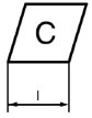
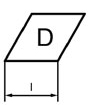
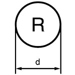
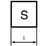
| Designation | Insert shape and angle | Normal clearance angle | Tolerance class | Chipbreaker and clamping type | Edge length | Insert thickness | Corner radius / finishing edge | Cutting edge condition | Cutting direction | |
| Example | C | N | M | G | 12 | 04 | 08 | - | E | N |
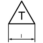
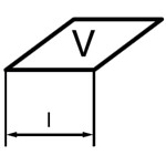
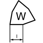
1. Insert shape and angle
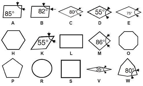
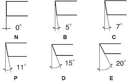
2. Normal clearance angle
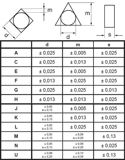
3. Tolerance class
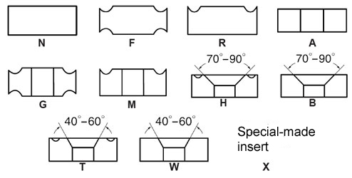
4. Chipbreaker and clamping style
5. Cutting edge length
|
|
|
|
|
|
|
|
l, d | |
| mm | cale | |||||||
| S4 | 04 | 03 | 03 | 06 | - | - | 3,97 | 5/32 |
| 04 | 05 | 04 | 04 | 08 | 08 | S3 | 4,76 | 3/16 |
| 05 | 06 | 05 | 05 | 09 | 09 | 03 | 5,56 | 7/32 |
| - | - | 06 | - | - | - | - | 6,00 | .236 |
| 06 | 07 | 06 | 06 | 11 | 11 | 04 | 6,35 | 1/4 |
| 08 | 09 | 07 | 07 | 13 | 13 | 05 | 7,94 | 5/16 |
| - | - | 08 | - | - | - | - | 8,00 | .315 |
| 09 | 11 | 09 | 09 | 16 | 16 | 06 | 9,52 | 3/8 |
| - | - | 10 | - | - | - | - | 10,00 | .394 |
| 11 | 13 | 11 | 11 | 19 | 19 | 07 | 11,11 | 7/16 |
| - | - | 12 | - | - | - | - | 12,00 | .472 |
| 12 | 15 | 12 | 12 | 22 | 22 | 08 | 12,70 | 1/2 |
| 14 | 17 | 14 | 14 | 24 | 24 | 09 | 14,29 | 9/16 |
| 16 | 19 | 15 | 15 | 27 | 27 | 10 | 15,88 | 5/8 |
| - | - | 16 | - | - | - | - | 16,00 | .630 |
| 17 | 21 | 17 | 17 | 30 | 30 | 11 | 17,46 | 11/16 |
| 19 | 23 | 19 | 19 | 33 | 33 | 13 | 19,05 | 3/4 |
| - | - | 20 | - | - | - | - | 20,00 | .787 |
| 22 | 27 | 22 | 22 | 38 | 38 | 15 | 22,22 | 7/8 |
| - | - | 25 | - | - | - | - | 25,00 | .984 |
| 25 | 31 | 25 | 25 | 44 | 44 | 17 | 25,40 | 1 |
| 32 | 38 | 31 | 31 | 54 | 54 | 21 | 31,75 | 1 1/4 |
| - | - | 32 | - | - | - | - | 32,00 | 1.260 |
6. Insert thickness
| Symbol | Thickness[mm] |
|---|---|
| 01 | 1,59 |
| T1 | 1,98 |
| 02 | 2,38 |
| 03 | 3,18 |
| T3 | 3,97 |
| 04 | 4,76 |
| 06 | 6,35 |
| 07 | 7,94 |
| 08 | 8,00 |
| 09 | 9,52 |
| 12 | 12,70 |
7. Corner radius / Finishing edge
| Symbol | Corner radius r |
|---|---|
| 02 | 0,2 |
| 04 | 0,4 |
| 08 | 0,8 |
| 12 | 1,2 |
| 16 | 1,6 |
| 20 | 2,0 |
| 24 | 2,4 |
| 32 | 3,2 |
| Symbol | Insert's clearance angle Κr | Symbol | Finishing edge's normal clearance angle αn |
|---|---|---|---|
| A | 45° | A | 3° |
| D | 60° | B | 5° |
| E | 75° | C | 7° |
| F | 85° | D | 15° |
| P | 90° | E | 20° |
| Z | inny kąt | F | 25° |
| G | 30° | ||
| N | 0° | ||
| P | 11° | ||
| Z | inny kąt |
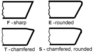
8. Cutting edge condition
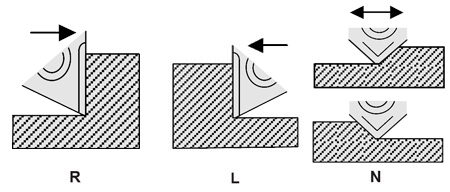
9.Cutting direction
Basic cutting conditions - TURNING
| Material group | Material group No | Brinell hardness [HB] | Corner radius 04 | Cordner radius 08 | Corner radius 12 | Vc [m/min] | |||
|---|---|---|---|---|---|---|---|---|---|
| ap | f | ap | f | ap | f | ||||
| Low carbon steel | 1 | 150 | 0,50 - 1,50 | 0,10 - 0,15 | 1,00 - 3,00 | 0,22 - 0,28 | 1,50 - 5,00 | 0,35 - 0,50 | 350 |
| 180 | 280 | ||||||||
| 210 | 250 | ||||||||
| Alloy steel | 2 | 180 | 0,50 - 1,50 | 0,10 - 0,12 | 1,00 - 3,00 | 0,22 - 0,28 | 1,50 - 4,00 | 0,32 - 0,45 | 270 |
| 230 | 230 | ||||||||
| 280 | 190 | ||||||||
| 320 | 170 | ||||||||
| High aloyt steel | 3 | 220 | 0,50 - 1,50 | 0,10 | 1,00 - 3,00 | 0,20 - 0,25 | 1,50 - 3,00 | 0,30 - 0,42 | 170 |
| 280 | 130 | ||||||||
| 320 | 110 | ||||||||
| 350 | 90 | ||||||||
| Austenic stainless steel | 4 | 210 - 250 | 0,50 - 1,50 | 0,12 - 0,15 | 1,00 - 3,00 | 0,18 - 0,32 | 1,50 - 5,00 | 0,35 - 0,52 | 230 |
| 5 | 230 - 270 | 0,50 - 1,50 | 0,10 - 0,12 | 1,00 - 3,00 | 0,18 - 0,25 | 1,50 - 4,00 | 0,32 - 0,48 | 190 | |
| 6 | - | 0,50 - 1,20 | 0,11 | 1,00 - 1,25 | 0,18 - 0,23 | 1,50 - 3,00 | 0,30 - 0,45 | 110 | |
| Ferritic stainless steel | 7 | annealed | 0,50 - 1,50 | 0,12 - 0,15 | 1,00 - 3,00 | 0,22 - 0,28 | 1,50 - 4,00 | 0,32 - 0,48 | 190 |
| Martensitic stailness stell | 8 | annealed | 0,50 - 1,50 | 0,12 - 0,15 | 1,00 - 3,00 | 0,22 - 0,28 | 1,50 - 4,00 | 0,32 - 0,48 | 190 |
| treated | 150 | ||||||||
| Grey cast iron | 9 | 140 - 250 | 0,20 - 1,50 | 0,08 - 0,15 | 1,00 - 4,00 | 0,18 - 0,35 | 1,00 - 5,00 | 0,35 - 0,60 | 270 |
| 230 | |||||||||
| 210 | |||||||||
| Nodular cast iron | 10 | 210 | 0,20 - 1,50 | 0,10 - 0,12 | 1,00 - 3,00 | 0,18 - 0,30 | 1,50 - 5,00 | 0,35 - 0,50 | 210 |
| 260 | 170 | ||||||||
| 310 | 150 | ||||||||
| Nickle based alloys | 11 | - | 0,20 - 1,20 | 0,10 - 0,12 | 1,00 - 3,00 | 0,18 - 0,28 | 1,00 - 3,00 | 0,30 - 0,42 | 35 |
| 38 | |||||||||
| 65 | |||||||||
| Titanium based alloys | 12 | - | 0,20 - 1,20 | 0,10 - 0,14 | 1,00 - 3,00 | 0,18 - 0,32 | 1,00 - 4,00 | 0,32 - 0,45 | 55 |
| 42 | |||||||||
| Aluminium (Si < 8%) | 13 | - | 0,20 - 5,00 | 0,12 - 0,25 | 0,20 - 5,00 | 0,15 - 0,50 | 800 | ||
| - | 450 | ||||||||
| For Alu group 13 please use Aluline grade PL 05 | |||||||||
| Aluminium (Si > 8%) | 14 | - | 0,50 - 5,00 | 0,12 - 0,20 | 0,50 - 5,00 | 0,15 - 0,40 | 0,50 - 5,00 | 0,20 - 0,60 | 250 |
| For Alu group 14 please use Aluline grade PL 10 | |||||||||