Lathe Chucks
Lathe Spindle Nose Mounting Systems
To determine which type of spindle nose mounting your lathe requires, consult the diagrams below, then read the chart beneath the appropriate diagram. Make the measurement required. This will give you the exact type of mounting for the lathe spindle nose.
American Standard Type D1 - Camlock
The Type D1 Camlock mounting is used on lots of Engine Lathe spindles. Each pin on the chuck side has a "D" shape cutout. For quick measurement, measure from center of spindle to center of pin, “D” (D=1/2F). When mounting, you use your chuck key to rotate a cam in the spindle side that pulls the pin in snug.
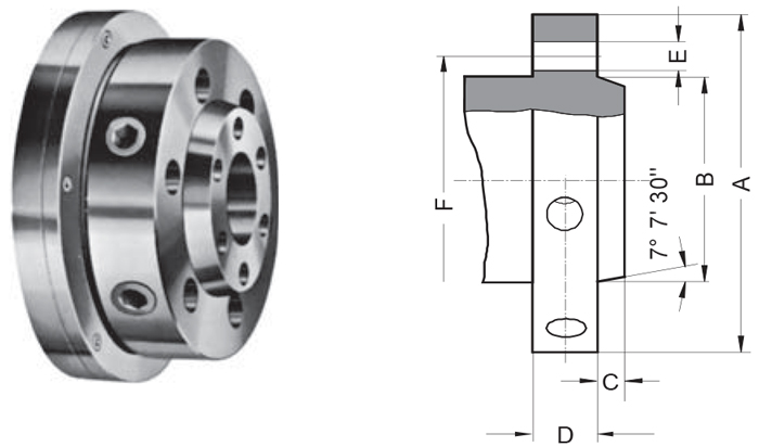
| Spindle nose size | A | Bmax | C | D | E | F |
|---|---|---|---|---|---|---|
| D1 - 3 | 92 | 53.983 | 11 | 32 | 3x15.1 | 70.6 |
| D1 - 4 | 117 | 63.521 | 11 | 34 | 3x16.7 | 82.6 |
| D1 - 5 | 146 | 82.573 | 13 | 38 | 6x19.8 | 104.8 |
| D1 - 6 | 181 | 106.385 | 14 | 45 | 6x23 | 133.4 |
| D1 - 8 | 225 | 139.731 | 16 | 50 | 6x26.2 | 171.4 |
| D1 - 11 | 298 | 196.883 | 18 | 60 | 6x31 | 235 |
| D1 - 15 | 403 | 285.791 | 19 | 70 | 6x35.7 | 330.2 |
| D1 - 20 | 546 | 412.795 | 21 | 82 | 6x42.1 | 463.6 |
American Standard Type Ax & Bx - Short Taper
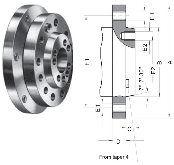
A1
| A1 | ||||||||
|---|---|---|---|---|---|---|---|---|
| Spindle nose size | A | Bmax | C -0.025 | D | E1 | F1 | E2 | F2 |
| A1 - 5 | 133.4 | 82.575 | 14.288 | 22.2 | 11x7/16-14 UNC | 104.8 | 8x7/16-14 UNC | 61.9 |
| A1 - 6 | 165.1 | 106.390 | 15.875 | 25.4 | 11x1/2-13 UNC | 133.4 | 8x1/2-13 UNC | 82.6 |
| A1 - 8 | 209.5 | 139.735 | 17.462 | 28.6 | 11x5/8-11 UNC | 171.4 | 8x5/8-11 UNC | 111.1 |
| A1 - 11 | 279.4 | 196.885 | 19.05 | 34.9 | 11x3/4-10 UNC | 235 | 8x3/4-10 UNC | 165.1 |
| A1 - 15 | 381 | 285.8 | 20.638 | 41.3 | 12x7/8-9 UNC | 330.2 | 11x7/8-9 UNC | 247.6 |
| A1 - 20 | 520 | 412.8 | 22.225 | 47.6 | 12x1-8 UNC | 463.6 | 11x1-8 UNC | 368.3 |
Type A: Tapped holes in fl ange (outer bolt circle) without inner bolt circle.
A2
| A2 | ||||||
|---|---|---|---|---|---|---|
| Spindle nose size | A | Bmax | C | D | E1 | F1 |
| A2 - 3 | 92.1 | 53.985 | 11.1 | 15.9 | 3x7/16-14 UNC | 70.66 |
| A2 - 4 | 108 | 63.525 | 11.1 | 19 | 11x7/16-14 UNC | 82.55 |
| A2 - 5 | 133.4 | 82.575 | 12.7 | 22.2 | 11x7/16-14 UNC | 104.8 |
| A2 - 6 | 165.1 | 106.390 | 14.3 | 25.4 | 11x1/2-13 UNC | 133.4 |
| A2 - 8 | 209.5 | 139.735 | 15.9 | 28.6 | 11x5/8-11 UNC | 171.4 |
| A2 - 11 | 279.4 | 196.885 | 17.5 | 34.9 | 11x3/4-10 UNC | 235 |
| A2 - 15 | 381 | 285.8 | 19 | 41.3 | 12x7/8-9 UNC | 330.2 |
| A2 - 20 | 520 | 412.8 | 20.6 | 47.6 | 12x1-8 UNC | 463.6 |
Type A1-A2 correspond ISO 702/I.
Tapped holes in fl ange (outer bolt circle) without inner bolt circle.
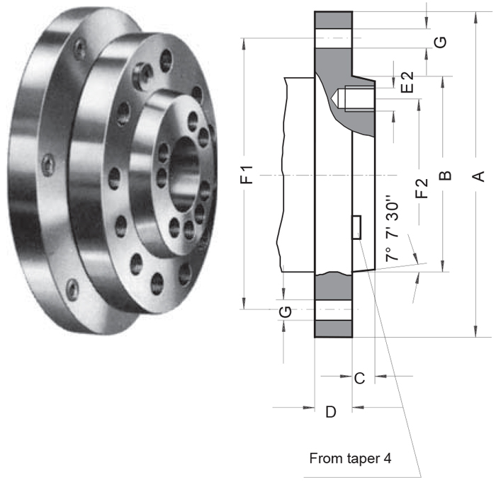
B1
| B1 | ||||||||
|---|---|---|---|---|---|---|---|---|
| Spindle nose size | A | Bmax | C -0.025 | D | G | F1 | E2 | F2 |
| B1 - 5 | 133.4 | 82.575 | 14.288 | 22.2 | 11x11.9 | 104.8 | 8x7/16-14 UNC | 61.9 |
| B1 - 6 | 165.1 | 106.390 | 15.875 | 25.4 | 11x13.5 | 133.4 | 8x1/2-13 UNC | 82.6 |
| B1 - 8 | 209.5 | 139.735 | 17.462 | 28.6 | 11x16.7 | 171.4 | 8x5/8-11 UNC | 111.1 |
| B1 - 11 | 279.4 | 196.885 | 19.05 | 34.9 | 11x20.2 | 235 | 8x3/4-10 UNC | 165.1 |
| B1 - 15 | 381 | 285.8 | 20.638 | 41.3 | 12x23.4 | 330.2 | 11x7/8-9 UNC | 247.6 |
| B1 - 20 | 520 | 412.8 | 22.225 | 47.6 | 12x26.6 | 463.6 | 11x1-8 UNC | 368.3 |
B2
| B2 | ||||||
|---|---|---|---|---|---|---|
| Spindle nose size | A | Bmax | C | D | G | F1 |
| B2 - 3 | 92.1 | 53.985 | 11.1 | 15.9 | 3x11.9 | 70.66 |
| B2 - 4 | 108 | 63.525 | 11.1 | 19 | 11x11.9 | 82.55 |
| B2 - 5 | 133.4 | 82.575 | 12.7 | 22.2 | 11x11.9 | 104.8 |
| B2 - 6 | 165.1 | 106.390 | 14.3 | 25.4 | 11x13.5 | 133.4 |
| B2 - 8 | 209.5 | 139.735 | 15.9 | 28.6 | 11x16.7 | 171.4 |
| B2 - 11 | 279.4 | 196.885 | 17.5 | 34.9 | 11x20.2 | 235 |
| B2 - 15 | 381 | 285.8 | 19 | 41.3 | 12x23.2 | 330.2 |
| B2 - 20 | 520 | 412.8 | 20.6 | 47.6 | 12x26.6 | 463.6 |
American Standard Type L - Long Taper
Widely used on industrial-class lathes from the late 1930s until the 1960s. The spindle nose has taper for centring and locating fittings, a key for positive location and a flanged retention nut.
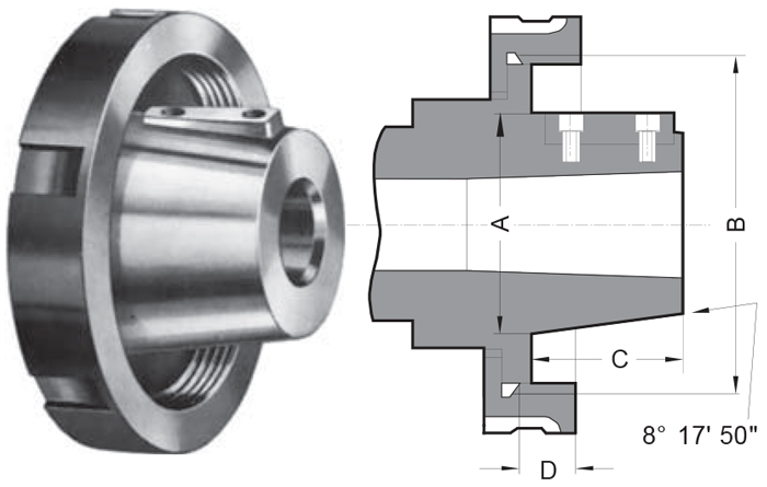
| Spindle nose size | A+0.051 | B | C | D | Driving key |
|---|---|---|---|---|---|
| L00 | 69.850 | 3 3/4-6 UNS | 50.800 | 14.288 | 9.525x38.1 |
| L0 | 82.550 | 4 1/2-6 UNS | 60.325 | 15.875 | 9.525x44.45 |
| L1 | 104.775 | 6-6 UNS | 73.025 | 19.050 | 15.875x60.32 |
| L2 | 133.350 | 7 3/4-5 UNS | 85.725 | 25.400 | 19.05x73.02 |
| L3 | 165.100 | 10 3/8-4 UNS | 94.425 | 28.575 | 25.4x82.55 |
Threaded Spindle Mount

| A | Bg5 | Cmin | D | E | F |
|---|---|---|---|---|---|
| M 20 | 21 | 30 | 6.3 | 10 | 20 |
| M 24 | 25 | 36 | 8 | 12 | 24 |
| M 33 | 34 | 50 | 9 | 14 | 30 |
| M 39 | 40 | 56 | 10 | 16 | 35 |
| M 45 | 46 | 67 | 11 | 18 | 40 |
| M 52 | 55 | 80 | 12 | 20 | 45 |
| M 60 | 62 | 90 | 14 | 22 | 50 |
| M 76x6 | 78 | 112 | 16 | 30 | 63 |
| M 105x6 | 106 | 150 | 20 | 40 | 80 |
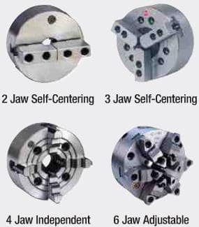
Chuck Types
Self-Centering Chucks are ideal for gripping cylindrical or concentric work because all jaws work in unison and automatically center the piece. Independent chucks are suited for gripping irregularly shaped workpieces or for eccentric operations because jaws work independently. Adjustable chucks operate like a self-centering chuck but are used where extreme accuracy is required. User may adjust within .0005 T.I.R.
MOUNTING INSTRUCTIONS:
LATHE MUST BE LEVELED WITH A PRECISION LEVEL
Chuck Mounting Information: Using Intermediate Plates -
For Standard Flat Back Lathe Chucks-
NOT for “Adjustable Run-Out” models (see separate instructions). When using a Chuck Adapter Plate to mount a flat back lathe chuck: 1. The lathe must be levelled with a precision level, this assures machining accuracy
2. Adapter plate or chuck plate is to be mounted on lathe spindle
3. A skim facing cut across the full face of the adaptor must be made. This assures that the face is at 90° to the centerline of the lathe spindle
4. The chuck plate has a boss onto which the recess in back of the chuck must mount. Turn the boss to fit tightly into the chuck body. The accuracy of this operation is directly relative to best results
5. Turn the O.D. of the chuck plate to match the chuck --- not always the same size of the chuck body, especially with 4 jaw independent chucks
6. In most cases the chuck has threaded holes in the chuck body, to accept mounting bolts, or the chuck plate has threaded holes, for chucks having through holes in the body for front insertion. In some instances it may be necessary to transfer hole locations and drill clearance holes
7. “A” type adaptors come in two versions: A-1 has two bolt circles (inner & outer), A-2 has a single bolt circle (outer) of tapped holes. The chuck adaptor is fastened to spindle separately, then the chuck is fastened to the plate
8. Lathes having threaded spindle noses follow similar procedures 1 thru 6
Chuck Mounting Information: Using Intermediate Adaptors - For ADJUSTABLE Run-Out Chucks, known as: “Adjust-Tru”, “Set-Tru”, “Zero-Set”, “Set-Rite”, “Hi-Tru”, “Accu-Chuck”.
This type of chuck is designed so that the chuck body can be moved by utilizing adjusting screws. A ground pin is held firmly in the chuck mounted on the lathe. The pin is trammed with a test indicator and the adjusting screws used to correct the run-out. The design of the chuck adaptor permits the chuck adjusting screws to contact an extended boss on the plate, facilitating adjustment. Each brand chuck requires its matching adaptor - same manufacturer or specific identification - they are not interchangeable (unless so indicated). These adaptors are to be “zeroed in” prior to actually mounting the chuck by taking a skim facing cut across the flange. All other dimensions should be compared to the back of the specific chuck and machined accordingly, if necessary. Once the mounted chuck has been “zeroed-in” in all respects, the chuck must be “locked” into the adjusted position. Double check with ground pin and test indicator.
Note - Plain Back Chucks Require Adapter or Converter Which May Require Machining to Fit Back of Chuck